3D Camera Mount - Background
Tracking the motion of particles in 2D under the microscope is easy: you just watch them moving around in the focal plane, e.g. Figure 1 here. However, to get a complete picture of the motion and location of particles within cells, it's also necessary to be able to track their motion in the z-direction; that is, in the dimension perpendicular to the focal plane. This is less easy! One not-so-hard way to do this is to introduce a z-dependent astigmatism into your images through the use of a cylindrical lens in the light path, e.g. Huang et al, Science 2008 for 3D super-resolution STORM imaging. The cylindrical lens distorts the point spread function of your particle into an elliptical shape, and the shape and degree of distortion can be calibrated to allow you to determine the z-position of an object with ~20 nm resolution.
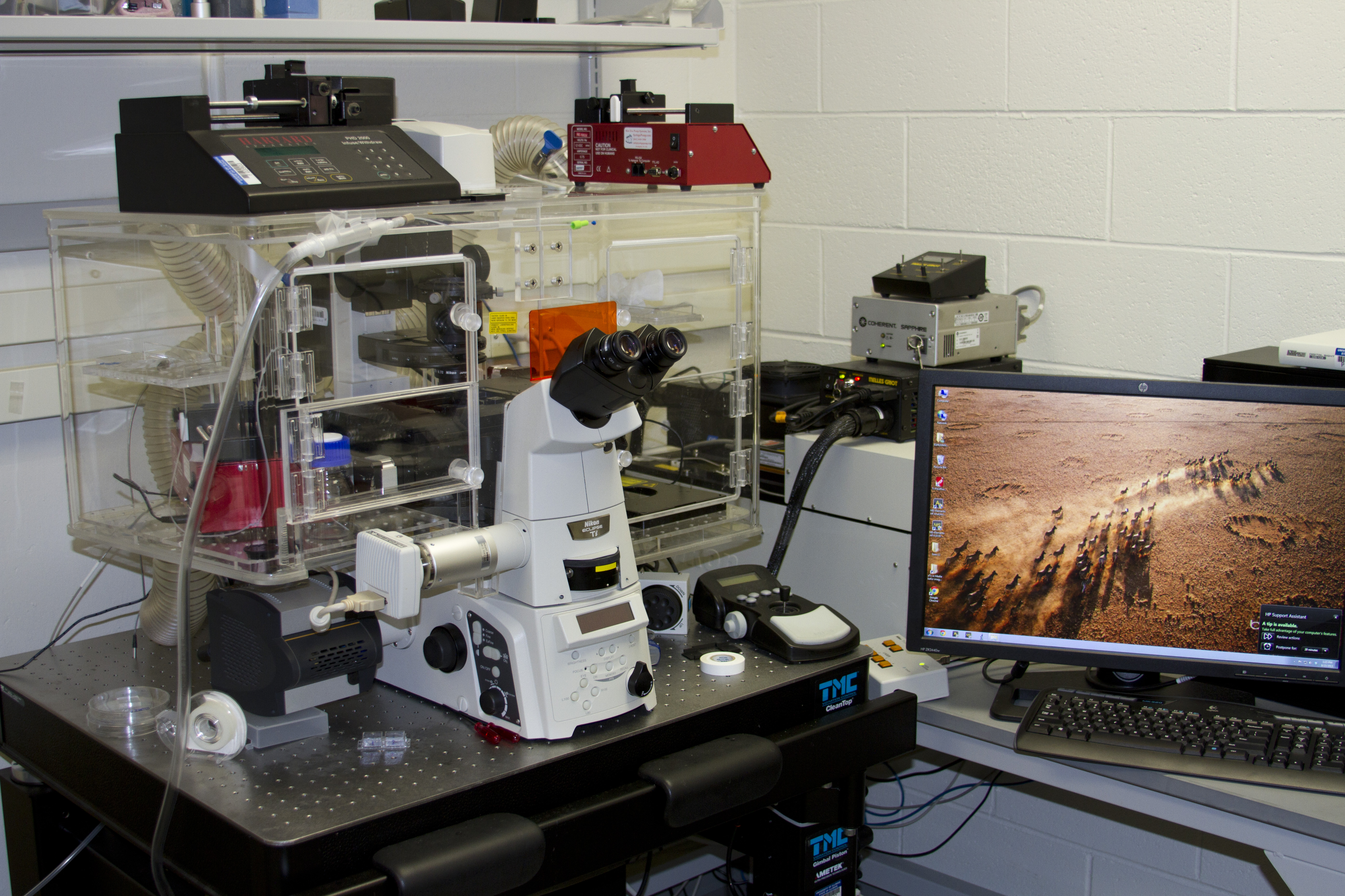
Figure 1: My fancy Nikon Eclipse TiE single molecule microscope
If you have built your own custom microscope, sticking a cylindrical lens into the light path anywhere you want is a piece of cake. However, when starting up my lab, putting together and troubleshooting a custom-made TIRF microscope was not where I wanted to spend my time and energy. So I bought a pre-built Nikon Eclipse TiE microscope (Figure 1).
One disadvantage of buying a microscope is that there are not many places where you have easy access to the light path to introduce the cylindrical lens. Of course, you can buy an add-on to allow you to do this; however, Nikon currently only sells a cylindrical lens mount as part of their N-STORM package, which costs ~$100k! Yikes. That is one spicy meatball.
While I was at Princeton, I played around with 3D imaging, and I machined and anodized a few aluminum cylindrical lens holders that will slide into a port underneath the filter cube carousel of a Nikon microscope (Figure 2). This works just fine for unstructured epifluorescent illumination. However, single molecule work requires highly focused laser illumination, and introducing the cylindrical lens at this point of the light path distorts the incoming laser beam as well as the outgoing image! That is no good, and therefore we need to look for another place to put the lens.
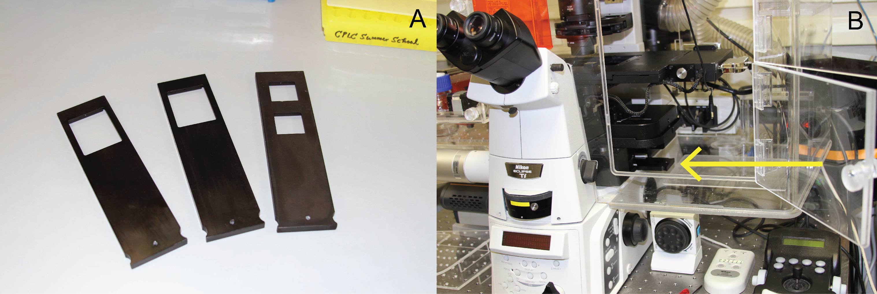
Figure 2: (A) My old machined and anodized aluminum cylindrical lens holders. They are beautiful, but alas! (B) One of the lens holders in the port under the filter carousel (highlighted by yellow arrow)
After the filter cube carousel, the next place you have easy access to the light path is when the image exits the microscope body through the camera ports. So, if we can modify the mount that attaches the camera to the port to hold our lens, we are in business! Unfortunately, these days I do not have much time to play around in the machine shop (*sigh*), and I didn't want to pay the fees (and suffer the indignity) of getting somebody else to machine it for me. So I used this problem as an excuse to buy a 3D printer, which we can use to quickly mock-up and print whatever new parts or modifications we can imagine! And so the first thing I designed was a new camera mount to hold cylindrical lenses to save myself $100k! (Well, actually $97k... the printer was ~$3k)
Printing and Prep Work
Here's the new camera mount being printed!

Figure 3: (A) The printer in action! We're about halfway done here. The full job at the highest printing resolution takes ~9 hours. Forgive the gnarly kapton tape on the printing surface! (B) What comes out of the printer. (C) The camera mount after removal of the supporting plastic.
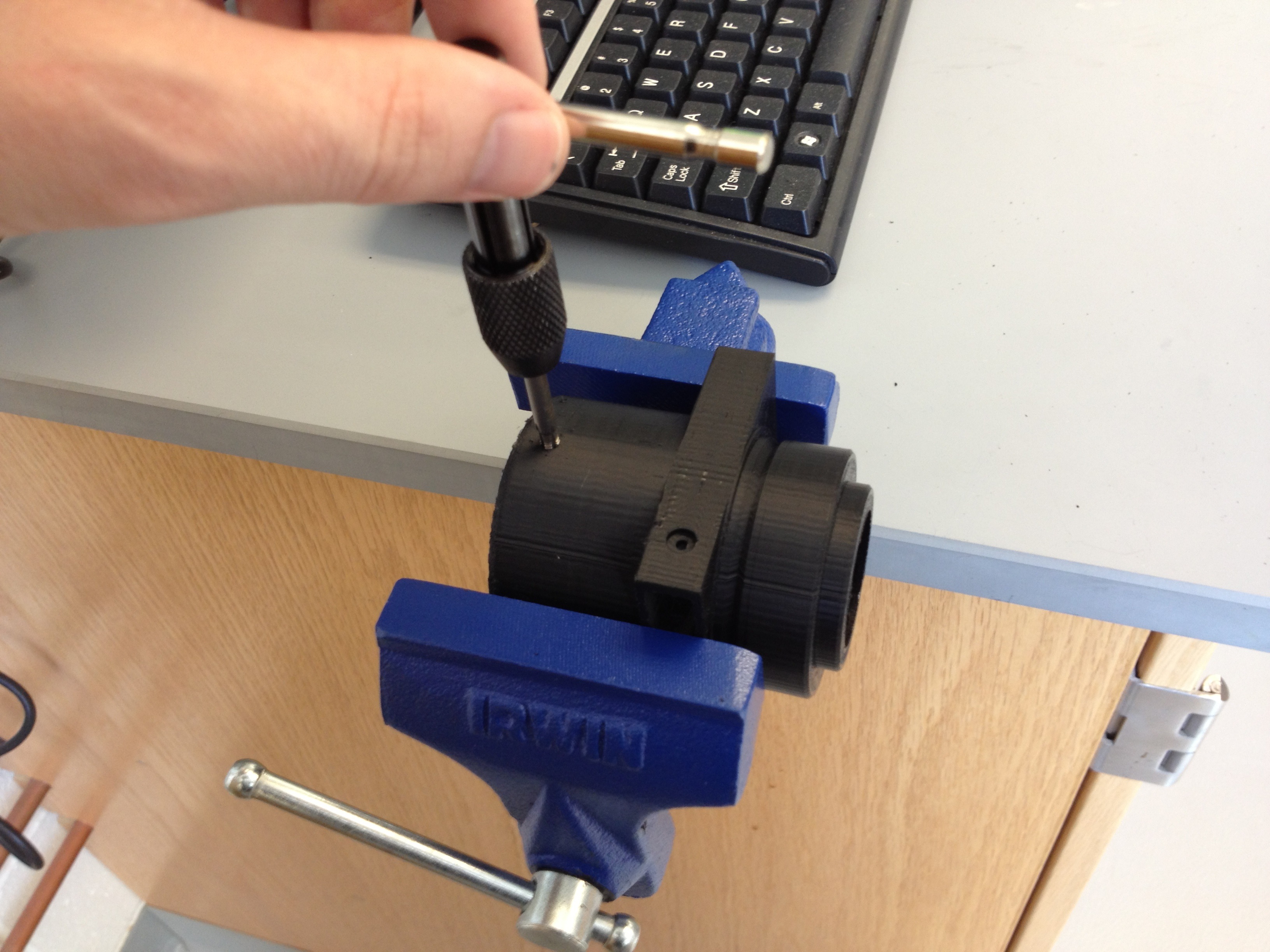
Figure 4: Just me, tappin' some holes.
To hold everything firmly in place, the microscope uses several 4mm set screws. The printer could probably print the screw holes including the threads, but I prefer to tap them myself (Figure 4). I used a 4mm-0.70 screw tap for the microscope set screws, and a smaller 3mm-0.50 tap for the lens holder set screw.
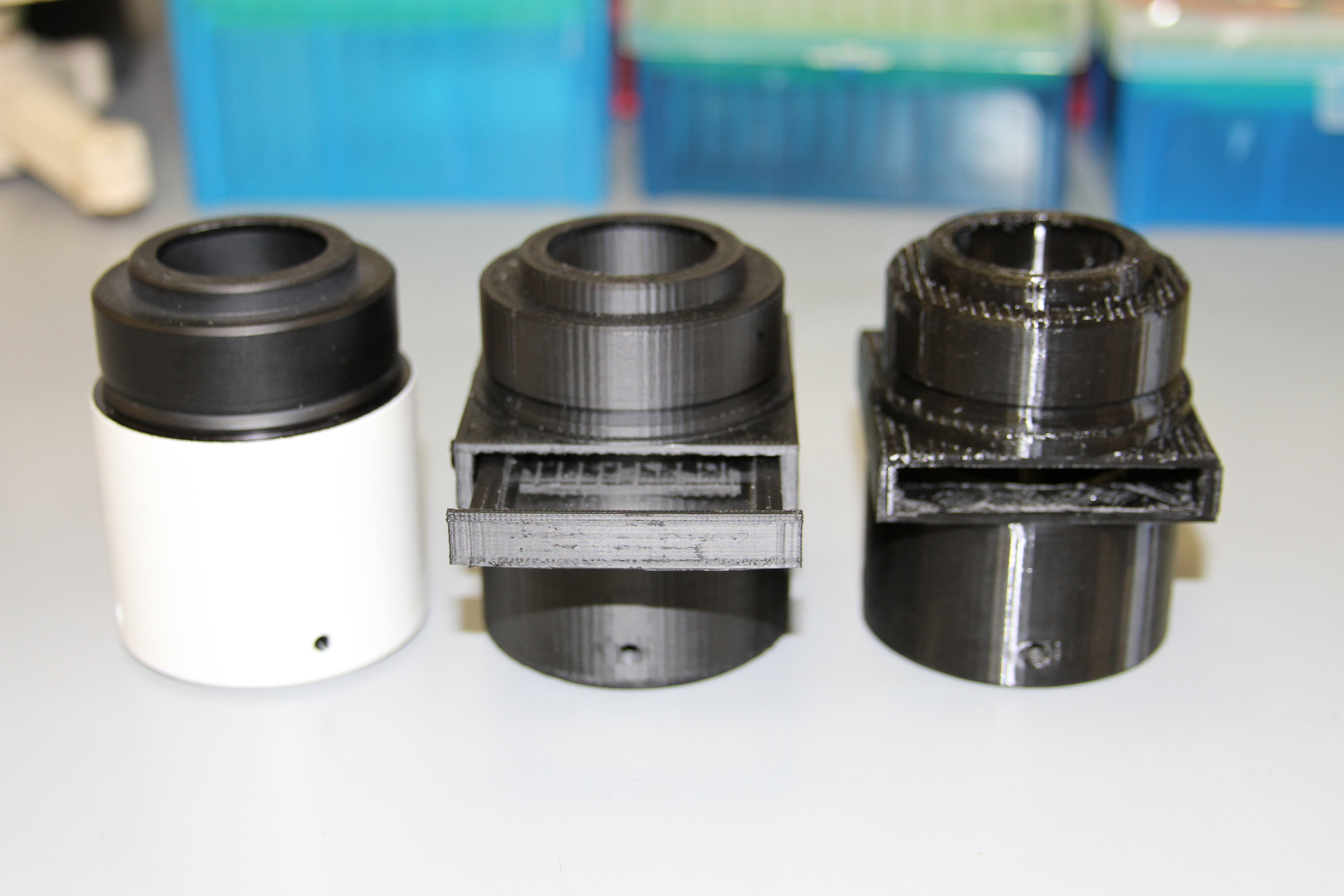
Figure 5: The final product.
And here is the finished camera mount and lens holder compared to the original Nikon camera mount on the left (Figure 5). The middle one is printed with ABS plastic, while the one on the right is printed with PLA. The PLA is harder and more sturdy, but is unfortunately far more shiny and reflective; not a good thing for microscope parts!
And, finally, here is the new camera mount, mounting a camera (Figure 6)!
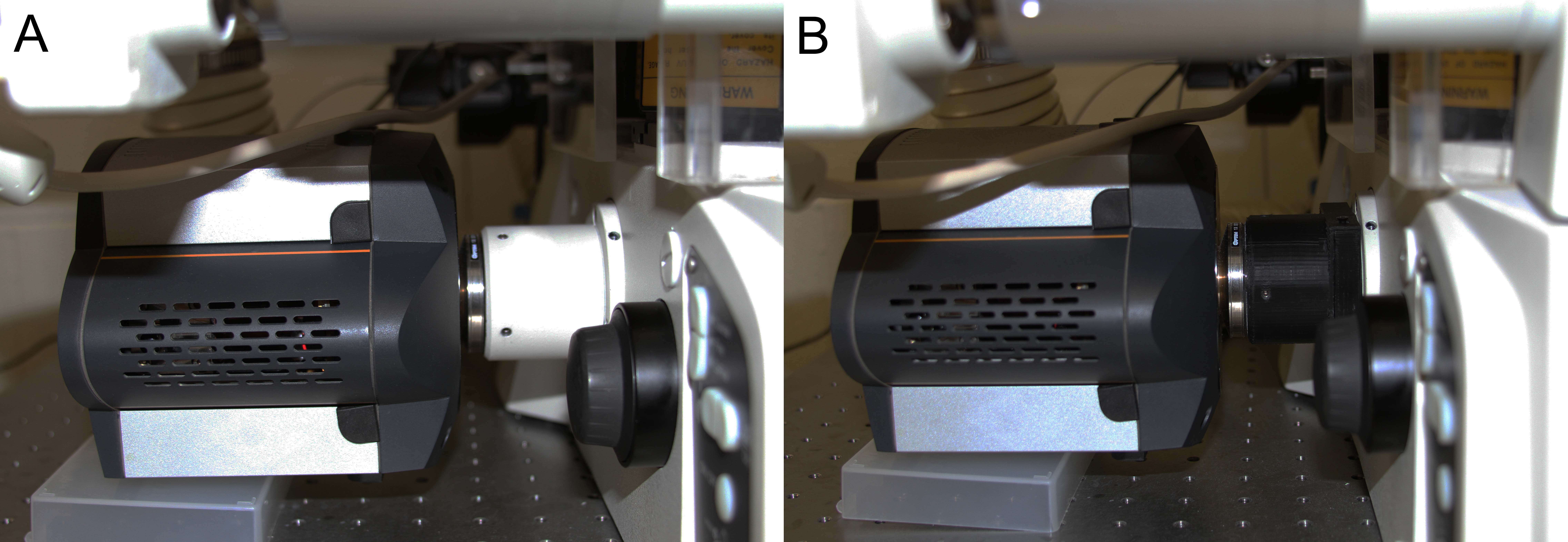
Figure 6: (A) Our Andor camera with the original mount. (B) The camera with the new mount!
Does it work?
Of course! Observe:
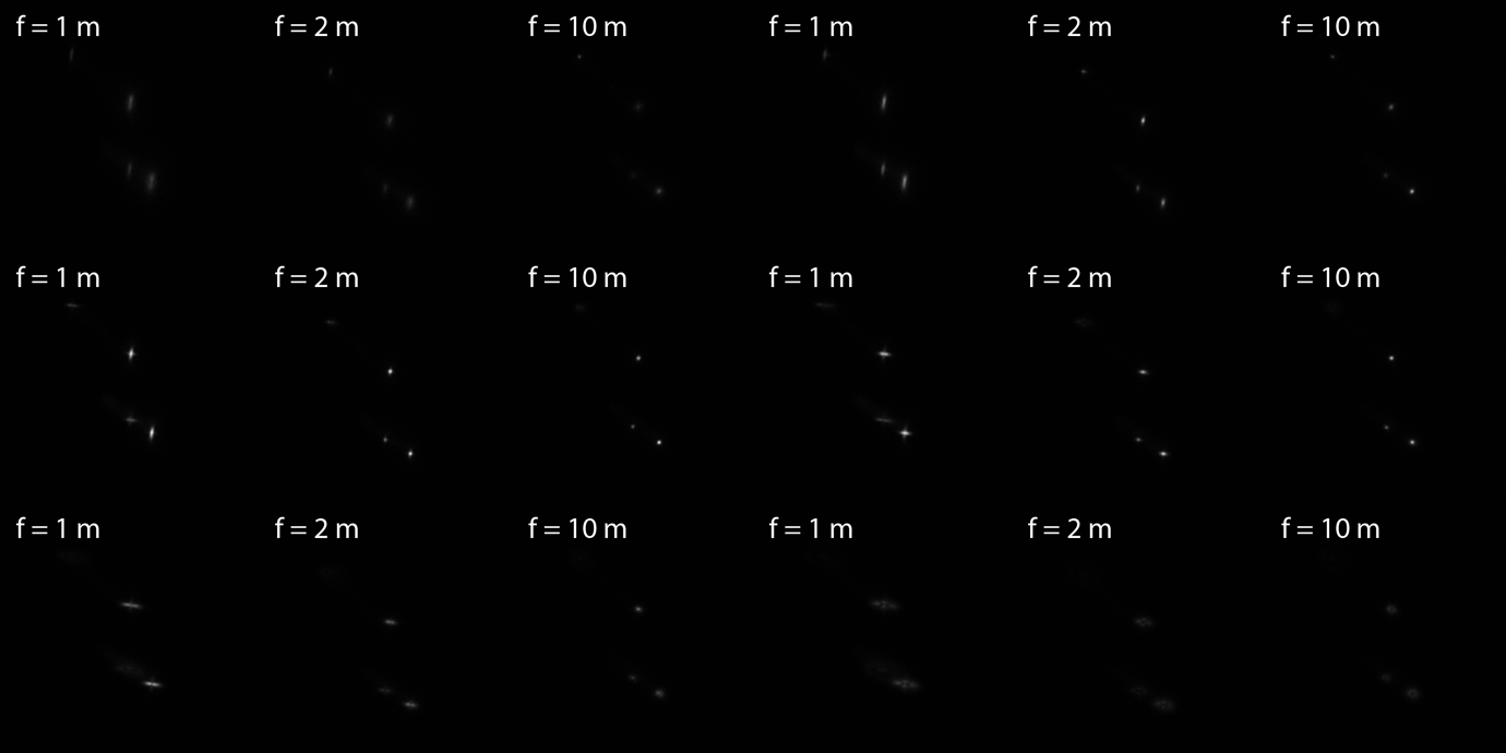
Figure 7: The 3D camera mount in action! The animations are a z-stack as we progressively move the stage ~200 nm in the z-direction per frame using a 1 m focal length (left), 2 m focal length (middle), or 10 m focal length (right) cylindrical lens. The f = 10 m lens is a little too weak to see any effect. You can even immediately tell that some of the spots are on opposite sides of the cells!
We are looking at E. coli expressing mRNAs tagged with MS2-EGFP magnified 400x, same as Figure 1 here. You can see that, as we scan through z, the shape and degree of distortion of each of the fluorescent spots changes. This distortion can be calibrated such that, when taking a single image and fitting the spots, you can tell where in z they are relative to the focal plane!
What's next?
I recently learned that Nikon's NIS Elements software, which we use to run our microscope, can send TTL signals to communicate with custom external hardware... we are going to redesign and automate this thing to allow us to dynamically switch between 3D and 2D imaging at the push of a button!